As
you might imagine, HyperMatter is capable of
accomplishing considerably more sophisticated
animation than the previous simple example. In
fact, HyperMatter’s comprehensive toolset
makes creating impossible effects and animation
not only possible, but practical even when faced
with demanding scripts and tight production
deadlines. The following tutorial is designed to
give you a taste of what you can accomplish using
just a few of HyperMatter’s advanced
capabilities.  Although the following
scene file contains a somewhat complex HyperMatter
animation, the tutorial has been streamlined to
take you quickly through the process used to
create character animation with HyperMatter. You
will see how HyperMatter Solids can be applied to
an entire character or just to selected parts of
a character. You will also see how HyperMatter
Constraints can be used to control both object
motion and shape. In this tutorial you will:
•
Examine an advanced HyperMatter character
animation
•
Compare the differences between Object and
Sub-Object Solids
•
See how Constraints affect Object motion and
deformation
•
Enable and Disable selected HyperMatter Solids to
enhance performance
Download Cannon.zip
(650K)
View
the Animation
You
will begin by opening CH2_dd01.max, a 3DS MAX
scene depicting a mouse which is fired from a
cannon and crashes into a platform as another
mouse recoils from the impact. The collision uses
a hidden HyperMatter Walls Object with the floor
aligned to the CrashPlatform. The animation opens
as SaluteMouse salutes the camera and slowly
disappears into the cannon. Because SaluteMouse
is not required to deform or react, a keyframed
MAX mesh was used. At frame 50 SaluteMouse stops
and H_CannonMouse begins its ascent from the
cannon and flies wobbling, through the air.
H_CannonMouse
is a Object Level Solid which contains all of the
character’s geometry and thus is entirely
under HyperMatter control. As you will see, the
character’s trajectory, as well as its
deformation is guided by a combination of
HyperMatter substance properties along with
several Constraints.
Start
3DStudio MAX and open CH2_dd01.max.
A
scene is loaded consisting of three mouse
characters, a cannon, and two round platforms.
The
SaluteMouse descends into the cannon as the
camera orbits and dollies back. The cannon then
fires and recoils as H_CannonMouse exits the
cannon and flies through the air toward the
CrashPlatform. On impact H_CannonMouse collapses
like an accordion and rolls about from inertia.
As
H_CannonMouse flies through the air,
H_SpectatorMouse follows its motion path finally
reacting to the impact at frame 216.
H_SpectatorMouse is jolted from the impact of
H_CannonMouse, and as its head rotates toward
camera its ears , snout, and left hand react to
the changes in its head and body positions.
Object
Level Solid - H_CannonMouse
These
two mouse characters demonstrate the two
essential methods of applying HyperMatter Solids;
at Object Level and at Sub-Object Level.
Generally speaking, Object Level Solidify is
easiest to apply and works well when you want an
entire character or object to act as if it is
embedded in a solid block of HyperMatter
material. In this case, the object is completely
controlled by HyperMatter’s physically-based
animation. Alternatively, you can apply
HyperMatter at Sub-Object level. This offers the
distinct advantage of enabling you to use
HyperMatter to enhance keyframe
animation—your characters can react
naturally to kinematic motion.
H_CannonMouse
is an Object Level Solid. HyperMatter is applied
to the entire character because you want the
entire character to be completely controlled by
HyperMatter Dynamics. This assures that its
entire body reacts to the initial force of the
cannon blast, and its impact with the
CrashPlatform.
In
the following steps you will look at
H_CannonMouse and see how Solid Object Solidify
was used to create a HyperMatter Solid from the
entire character. You will also see how
Solid’s Resolution and Fit direction were
set up for the character. The HyperMatter
Solid’s Fit and Resolution should be
designed to optimize the fit around the geometry
while minimizing the number of points in the
Solid Object, thus minimizing processing time.
Fit is important because it is the HyperMatter
Solid Objects and not the character’s
geometry that collide with each other. 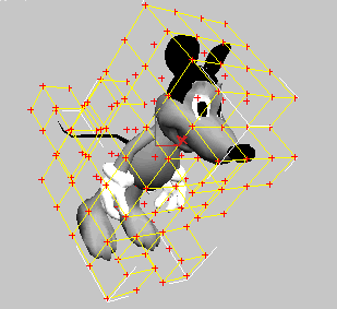
Resolution
is significant because of its impact on
processing time. The memory and time required to
process a HyperMatter animation is based on two
essential issues. The first issue is the number
of points comprising each Solid Object
(Resolution) and the second issue is the number
of times per frame that Hypermatter evaluates
these Points (Sampling Rate). The memory and
processing requirements of Solid Objects increase
linearly with respect to the number of
HyperMatter points in the Solid Object. This is
related to the cube of the Resolution value. For
example, if you Solidify a cube-shaped object at
a Resolution of 4 the resulting Solid Object will
require up to 4 x 4 x 4 = 64 points. If you
increase the Resolution to 5, the object will
require 5 x 5 x 5 = 125—nearly twice the
number of points and essentially twice the
processing time. Many times, relatively low
Resolution HyperMatter objects provide excellent
results.
Next
you will examine the Resolution of the previously
Solidified H_CannonMouse.
1.
Use Select by Name and select H_CannonMouse.
2.
Select the Display Panel, click Hide Unselected
and Zoom Extents.
The
H_CannonMouse geometry is displayed in the view.
A black HyperMatter Solid envelopes the
character.
3.
Select the Modify Panel, close the Modifiers
rollout, and click Automatic Solidify from the
HyperMatter Control rollout.
Automatic
Solids rollout appears.
4.
Click the Resolution up arrow.
Topology
Change Warning dialog appears, warning you that
you are about to Solidify.
5.
Click OK and click to increase the Resolution
from 3 to 6 while viewing the mouse in the Front
and Top views.
With
each mouse click the Solid’s Resolution is
increased by one cube in the direction specified
by the Fit. As Resolution increases the
HyperMatter Solid becomes more detailed and more
closely follows the mouse’s contour, however
as you increase the Resolution you also increase
HyperMatter’s processing time.
6.
Click to decrease the Resolution from 6 to 1.
With
each mouse click, the Solid’s Resolution is
decreased by one cube in the direction specified
by the Fit. As the Resolution decreases,
HyperMatter Solid becomes less detailed and the
Solid just slightly suggests the mouse’s
contour. As you decrease Resolution, you reduce
HyperMatter’s processing time.
7.
Select Edit/Fetch.
The
original scene is restored.
H_CannonMouse
Animation
The
Lifespan is the frame interval within which
HyperMatter Solids are controlled by HyperMatter
Dynamics. In this animation H_CannonMouse’s
Lifespan begins at frame 50. Prior to that time,
the mouse would be subject to 3DS MAX MAX
kinematic animation. However, in this case, no
MAX keyframes are used.
H_CannonMouse
Constraints 
Next
you will examine a few of the Constraints applied
to the H_CannonMouse character. A Constraint is a
control applied to a Part which affects the
natural motion of the Part in some way.
HyperMatter provides a range of Constraints
including Collide—which enables collisions
between Solid Objects—Velocity for constant
speed in a specified direction, and Set which
freezes a Solid’s shape. You can apply any
number of Constraints to one or more Points or
Parts in a Solid Object. Furthermore, each
Constraint also has its own associated Lifespan.
This enables you precisely to control
HyperMatter.
H_CannonMouse
uses four Constraints; Velocity, Set, and two
Angular Velocity Constraints. It also uses three
Selection Sets; Interior, All, and Body which are
used to constrain different areas of the
mouse’s body.
The
Velocity Constraint is used to simulate the
violent force of the cannon blast on the
mouse’s body. It is applied on all three
axes from frame 51 to frame 61. The first Angular
Velocity Constraint causes the mouse to rotate
around the Y axis and to plunge head first toward
the collision point. It is applied to the entire
Solid from frame 51 to 58. This assures that the
timing of the rotation will produce the desired
approach angle.
The
Set Constraint is applied from frame 212 to 350
and is used to freeze the mouse’s shape in
the distorted shape that results from the
collision. The final Angular Velocity Constraint
from frame 212 to 220 causes the flattened mouse
to spin slowly toward camera.
Next
you will see how the mouse’s Constraints
were applied and you will examine each.
1.
Select H_CannonMouse, the Modify Panel, and click
to collapse the Modifiers rollout.
The
HyperMatter Control rollout appears and the
Command Column is optimized for viewing
HyperMatter rollouts.
2.
Select Sub-Object HyperMatter and click
Constraints from the HyperMatter Control rollout
The
mesh surrounding the H_CannonMouse turns bright
yellow indicating Sub-Object HyperMatter
selection level and the Constraints rollout
appears. There are several buttons (grayed out)
representing the Constraints that can be applied
to HyperMatter objects. Below the Constraints
buttons is the Constraints List, showing the
currently applied Constraints, and the
corresponding Named Selection Set.
3.
Click to highlight the first Constraint in the
list, VEL [Interior].
The
Interior Selection Set is highlighted. The
Constraints rollout becomes active and the
Velocity rollout appears below it. The X, Y, and
Z boxes are checked, and there are values entered
in each spinner window. The Value of 200 in both
the X and Z direction provide the initial force
at an angle about 45 degrees to the world X Y
plane. This is what shoots the mouse out of the
cannon. Note that the Lifespan only lasts for 10
frames, starting at frame 51. This means that a
constant velocity will begin abruptly at frame
51, then the mouse will be on its own when the
Constraint Lifespan ends at frame 61.
NOTE: Whenever you
select or apply a Constraint you must first
select or create a HyperMatter Part. A Part is a
named selection set of Solid Object points. A
Constraint can only be applied to a selected
Part.
4.
Click to highlight ANG [All]. 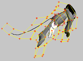
The
All Selection Set is highlighted. The Angular
Velocity Controller rollout appears. Angular
Velocity will cause an object to spin about the
X, Y or Z axis. In this instance, the Angular
Velocity constraint makes the mouse rotate from
the initial position inside the cannon into a
nose dive as it travels through its arc shaped
path to the landing platform. By applying Angular
Velocity about the Y axis for only 7 frames, the
animator has given the H_CannonMouse a gentle
push to get it to rotate slowly into a nose dive.
5.
Click to Highlight SET [body].
The
body Selection Set is highlighted. The Set
rollout appears, and the Lifespan number fields
read Start: 212, End: 350. The Set Constraint
causes the particular part to hold its current
shape,even if it is in the midst of deformation.
This is what keeps the H_CannonMouse in a folded
up state after it impacts the CrashPlatform. The
Set is applied to the body. The tail points were
intentionally left out of the constraint
selection so that the tail would be free to flop
around as the mouse moves.
6.
With SET [body] selected, click Enabled in the
Constraints rollout.
The
body Selection Set is highlighted. The Set
Constraint is temporarily disabled.
7.
Click Display Preferences from the HyperMatter
Control rollout and click to deselect Solid.
The
yellow HyperMatter Solid is hidden. This provides
an uncluttered view of the character.
8.
Play the animation.
The
mouse now bounces off of the landing platform and
maintains its shape and rubber-like consistency. 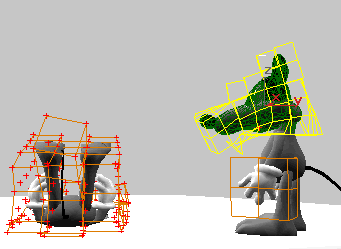
9.
Click to enable the Set Constraint, and highlight
ANG [All].
The
All Selection Set is highlighted. A second
Angular Velocity Controller is applied to the
mouse. A value of 1 is applied about both the X
and Y axis starting at frame 212. This will
provide some rotational noise to the mouse after
frame 212 (after the mouse is squashed). This is
what makes the mouse’s body appear to be
affected by the inertia of its flight.
NOTE: For more
information regarding Constraints and how to
apply them, see Chapter 6, Constraints &
Forces.
Sub-Object
Level Solids - H_SpectatorMouse
You
have seen briefly how HyperMatter works and how
it can move and deform a character based on real
world physics alone. In the previous animation,
H_CannonMouse is fully controlled by HyperMatter
Dynamics, however H_SpectatorMouse is only under
partial HyperMatter control. Its head and left
hand are Sub-Object Level Solids and thus react
to the keyframed animation of the remainder of
the character.
Next
you will see how Sub-Object Solids work and
enable you to make selected portions of a
character react not only to physics but to
keyframe animation that has been applied to the
object prior to Solidification.
1.
Go to the MAX Display panel; Hide H_CannonMouse
and Unhide H_SpectatorMouse.
2.
Click Zoom Extents All and change the CannonCam
view to SpectatorCam.
SpectatorCam
gives you a close up view of H_SpectatorMouse.
3.
Select H_SpectatorMouse and go to the Modify
panel.
The
mouse is selected.
Note that there are
two orange HyperMatter Objects; one which
envelopes the mouse’s head and a second on
its left hand.
4.
Select Sub-Object HyperMatter from the Modifier
Stack rollout.
The
HyperMatter Solid Objects pull down is active and
SO_SpectatorMouse1, the sub-object enveloping the
mouse’s head, is selected and highlighted
yellow.
TIP: You can select
sub-object Solids either by clicking the Solid in
a View or using the HyperMatter Solid Objects
pull down.
H_SpectatorMouse
Animation
H_SpectatorMouse
consists of two Solids, both of which are
controlled by HyperMatter for the entire
animation. These objects are joined to the
Control Object so that wherever it goes, the
Sub-Object Level Solids follow. This is what
makes it possible to have both the mouse’s
head and hand react to any keyframe motion that
is applied to the character before HyperMatter.
H_SpectatorMouse
follows H_CannonMouse through its flight, and
collision. It also is jolted by
H_CannonMouse’s impact. Finally
H_SpectatorMouse’s ears and snout react to
its head motion as it follows H_CannonMouse and
nods toward the camera at the end.
H_SpectatorMouse
Constraints 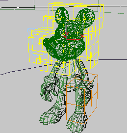
H_
SpectatorMouse has six Constraints applied to the
head Solid Object
(SO_SpectatorMouse0)—Orientation, Angular
Velocity, two Fix and two Follow Constraints. The
Fix [Join] is automatically applied to any
Sub-Object Solid. This consists of a Fix
constraint that is applied to a default Part
named Join. The Join Part provides a boundary
between the Sub-Object Level Solid and the
remaining Snapshot Geometry. It is linked to the
Control Object by a Fix Constraint.
The
two Follow Constraints lock selected points to
animated dummy objects. This enables the
mouse’s head to follow H_CannonMouse though
the air from frame 0-310, for instance.
The
Angular Velocity Constraint adds some head
rotation around Z at the end of the animation.
The second Fix Constraint localizes the motion in
the head to just the nose and ears for frames
310-350.
The
hand Solid, SO_SpectatorMouse1, has only the
default FIX [Join] Constraint applied.
The
hand Solid reacts to the keyframed movement of
the non-Solidified Snapshot Geometry.
1.
Select the Modify Panel, click to select
H_SpectatorMouse, and select SO_SpectatorMouse0
from the HyperMatter Solid Objects pull down.
The
HyperMatter Solid around the mouse’s head is
highlighted yellow.
2.
Click Constraints and select FOL
[nose]->SpecNoseDummy Constraint from the
Constraints list. 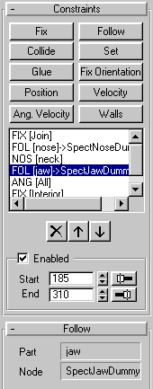
The
nose Selection Set is highlighted and the Follow
rollout appears. The nose Selection Set is
constrained in the X, Y, and Z axes from frame
0-310. This in effect forces these points and
therefore the remaining HyperMatter Solid to
track the path of the SpecNoseDummy Object.
3.
Click the ORI [neck] Constraint.
The
neck Selection Set is highlighted. No Spin keeps
the associated vertex Selection from changing its
orientation. In this case, the neck is to remain
stationary while the head turns.
4.
Click the ANG [all] Constraint.
The
All Selection Set is highlighted. This Constraint
helps to create a more exaggerated head movement
as the mouse’s head snaps over to look at
the camera.
5.
Click to Disable ANG [all] and create an AVI
preview using the SpectatorCam view.
The
animation shows frames 250 through 350 from the
SpectatorCam view. Notice that the head
doesn’t have as expressive a movement. The
Angular Velocity was applied to help make the
wobble more pronounced, and to increase the speed
of the head rotation so that the ears and nose
will wobble more when the head snaps into its
final position.
7.
Select FIX [Interior].
The
Interior Selection Set is highlighted. The Fix
Constraint makes the inside portion of the
mouse’s head freeze in its current position
and shape. Without this Constraint, the head will
attempt to return to its original shape and
position. The Interior Part was used so that the
mouse’s ‘skin’ would appear to
slide over his ‘skeleton’.
8.
Experiment further with each Constraint. For
instance, try editing the Lifespan of the Angular
Velocity [All] and Fix [Interior] Constraints.
Experiment with the H_CannonMouse Constraints.
Try editing the Lifespan and X Z values for the
Velocity [Interior] Constraint. Also try editing
the Substance properties, such as the Elasticity
and Damping values, for each character.
Congratulations!
You’ve completed a very detailed
introduction to HyperMatter. None the less, you
have discovered just a part of the remarkable
power and flexibility of this unique plug-in.
Once again welcome to a whole new way of
producing natural physically based animation on a
PC. We hope you enjoy using HyperMatter as much
as we have creating it.


|